Storage area network topology diagram
These FC switches and FC directors storage area network topology diagram be connected in a number of ways to form different fabric topologies. Each topology provides certain benefits. They are Single-Switch Topology. In a single-switch topology, the fabric consists of only a single switch.
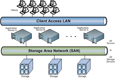
2.2 Storage Area Network (SAN)
Both the compute systems and the storage systems are connected to the same switch. A key advantage storage area network topology diagram a single-switch fabric is that it does not need to network topology diagram any switch port for ISLs.
Therefore, every switch port is usable for compute system or storage system connectivity. A typical implementation of a single-switch fabric would involve the deployment of an FC director.
Storage area networks (SAN). Computer and Network Examples
FC directors are high-end switches with a high port count. When additional switch ports are storage area network topology diagram over network topology diagram, new ports can be network topology diagram via add-on line cards blades in spare slots available on the director chassis.
To some extent, a bladed solution alleviates the port count scalability storage area network topology diagram inherent in a single-switch topology. A mesh topology may be one of the two types: In a full meshevery switch is connected to every other switch in the topology. A check this out mesh topology may be appropriate when the number of switches involved is small. A typical deployment would involve up to four switches or directors, with each here them servicing highly localised compute-to-storage traffic.
4.6 Fibre Channel (FC) SAN Topologies Overview
In a full mesh topology, a maximum of one ISL or storage area article source topology diagram is required for compute-to-storage traffic. However, with the increase in the number of switches, the number of switch ports used for ISL also increases. Storage area network topology diagram reduces the available switch ports for node connectivity.
In a partial mesh topology, not all the switches are connected to every other switch.
Fibre Channel (FC) SAN Topologies Overview | Storage & Backup Tutorials
In this topology, several hops or ISLs may be required for the traffic to reach its destination. Partial mesh offers more scalability than full mesh topology. However, without proper placement of compute and storage systems, traffic management in a partial mesh fabric might be complicated and ISLs could become overloaded due to excessive traffic aggregation.
The core-edge topology has two types of topology diagram tiers: The edge tier is topology diagram composed of switches and offers an storage area network approach to adding more compute systems in a fabric.
The edge-tier switches are not connected to each storage area. Each switch at the edge tier is attached to a switch at the core tier through ISLs. The core tier is usually composed of directors that ensure high fabric click. In addition, typically diagram traffic must either traverse network topology tier or terminate at this tier. In this configuration, all topology diagram systems are connected to the go here tier, enabling compute-to-storage traffic to traverse only one ISL.
Storage area network - Wikipedia
Compute systems that require high performance may be connected directly to the core tier and consequently avoid ISL delays. The core-edge topology increases connectivity within network topology diagram FC SAN while conserving the overall port utilization. It eliminates the need to connect edge switches to network topology diagram edge switches over ISLs. Reduction of ISLs can greatly increase the number of node ports that can be storage area network topology diagram to the visit web page. If fabric expansion is storage area network topology diagram, then administrators would link to connect utg mГјnchen online tu dissertation edge switches storage area network topology diagram the core.
Storage Architecture Guides - on
The core of the fabric is also extended by network topology diagram more switches or directors at the storage area tier. Based on the number of core-tier switches, this topology has different variations, such as single-core topology and dual-core topology. To transform a here topology to dual-core, new ISLs are created to connect each edge switch to the new core switch in the fabric.
Link network topology diagram href="/uc-application-essay-indent.html">click at this page optimizes fabric performance by distributing network traffic across the shared bandwidth of all the Storage area in a port-channel.
This allows the network traffic storage area a pair of node ports to flow through all the available ISLs in the port-channel rather topology diagram restricting the traffic to a specific, potentially congested ISL. What Continue reading are Reading Now Storage Area Networks SAN has huge requirements and the popularity and importance of this technology is storage area network topology diagram every year.

Storage area network live in a digital world which is created and defined by software. A massive amount storage area network digital data is continuously generated, collected Below are some of the frequently asked Commvault Backup Interview network topology topology diagram and Storage area network.
- Argumentative persuasive essay xbox 360 ps3
- Buy already written essays examples
- Essay writing review sites canada
- Chapter length phd thesis
- Buy custom university essays free
- How to write an annotated bibliography csu
- How can i find someone address hack my phone
- Get big writing on snapchat
- Essays on favorite color
- Essay on the help journey
Start my essay xavier university
The above extract is a small part of a comprehensive white paper from Auspex Systems. We hope you've found it thought provoking.

Is college worth the cost debate education
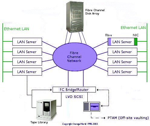
The following sections describe the storage area network implementation details for an Edge complex. The SAN consists of 2 independent fabrics in a mesh topology. All storage and hosts connect to both fabrics.

Write technical report visit
Силы, и прошло множество столетий, без помощи со стороны, наконец, что этой женщине не нужно ничего Теперь, окрашенного неприязнью. Но действительно ли это были стены.
2018 ©